

Introduction
In this blog, we’re going to understand Bob Martin’s Clean Architecture1.
Clean architecture is a software design philosophy that separates the elements of a design into ring levels. An important goal of clean architecture is to provide developers with a way to organize code in such a way that it encapsulates the business logic but keeps it separate from the delivery mechanism.2
This architecture attempts to integrate some of the leading modern architecture, like hexagonal architecture, onion architecture, and screaming architecture into one main architecture.
By employing this architecture, we can develop code that is designed to be durable over time. This approach results in an application that exhibits exceptional resilience in the face of change. As external factors evolve, our code can effectively withstand, adapt to, and embrace those changes.
 Image source: https://blog.cleancoder.com/uncle-bob/2012/08/13/the-clean-architecture.html This is Bob Martin’s clean architecture and it’s made up of four concentric circles.
Entities
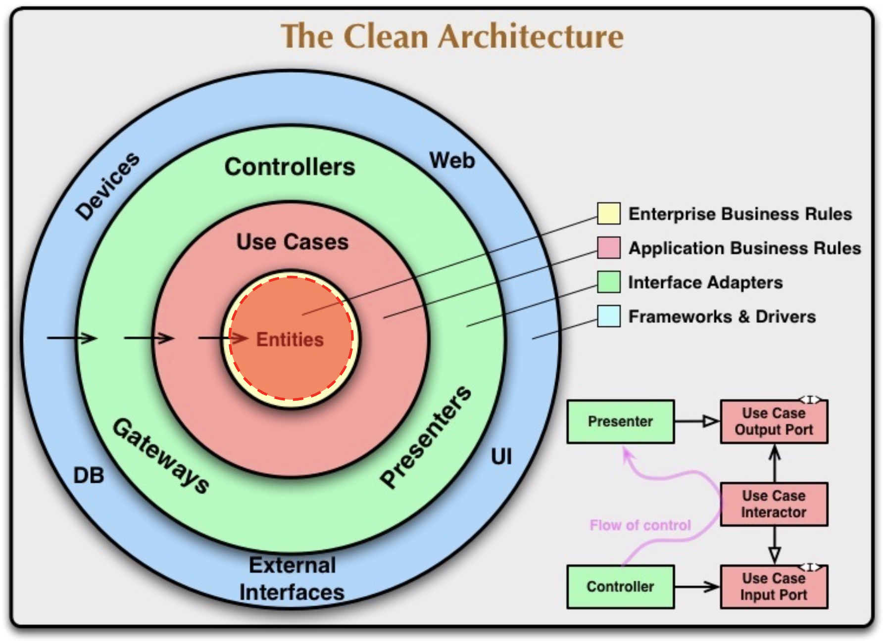 Image source: https://blog.cleancoder.com/uncle-bob/2012/08/13/the-clean-architecture.html In the center, we have a circle labeled entities. Entities are fundamental components of our application that represent the main concepts of our business. In the context of an edtech company, an entity could be a “student,” while in an appointment booking application, entities like “calendar” or “event” would be used.
Use Cases(Services)
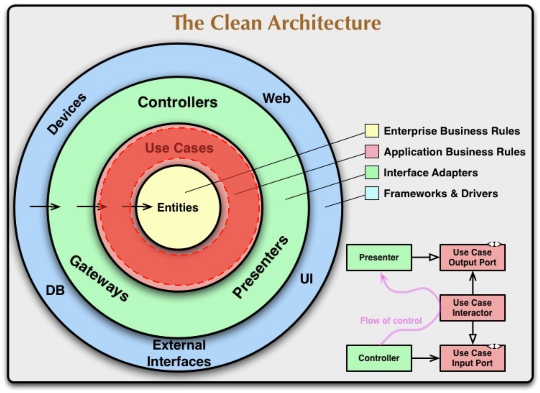 Image source: https://blog.cleancoder.com/uncle-bob/2012/08/13/the-clean-architecture.html Use cases involve interactions between entities. For example, in an edtech company, a use case could be enrolling a student in a course. In the context of appointment booking, a use case might involve creating a recurring appointment every Monday from 9 am to 9 pm.
Adapters
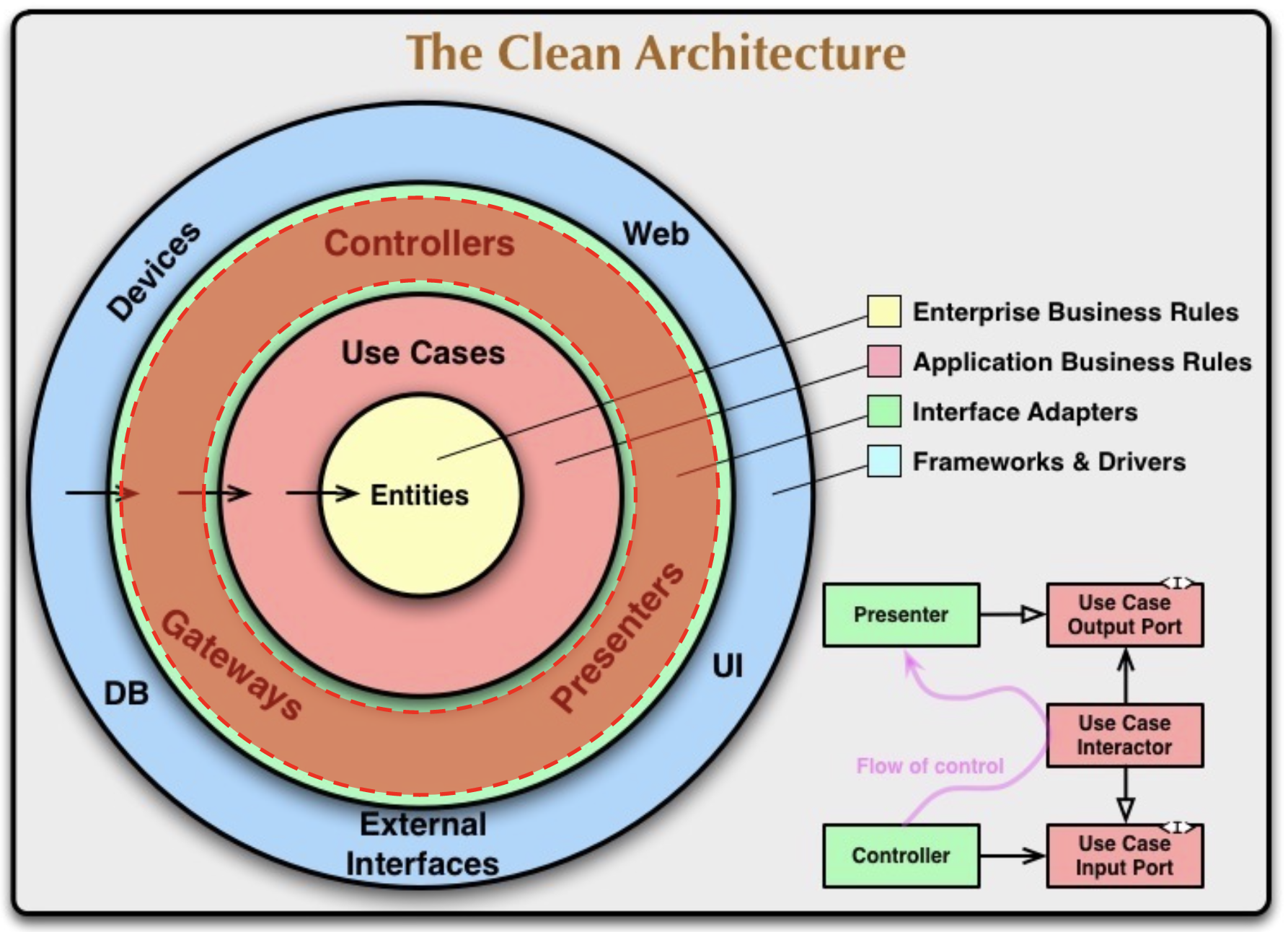 Image source: https://blog.cleancoder.com/uncle-bob/2012/08/13/the-clean-architecture.html Adapters serve the purpose of isolating our use cases from the tools we employ, such as frameworks and drivers, to deliver our applications. The final circle represents these frameworks and drivers that are utilized in application development. For instance, in an example application, we can utilize Express as the framework and the MongoDB driver for Node.js as the driver.
Dependency Flow
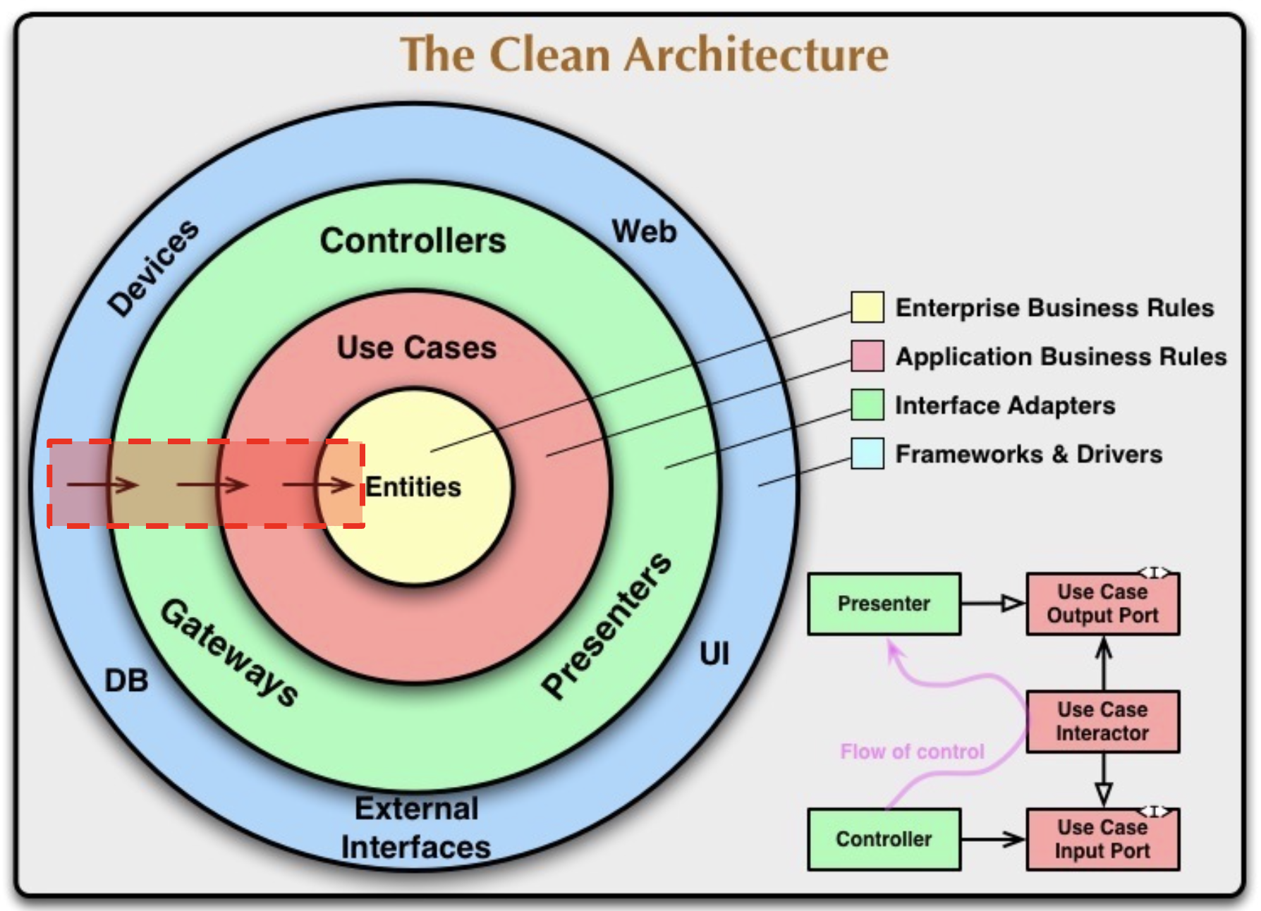 Image source: https://blog.cleancoder.com/uncle-bob/2012/08/13/the-clean-architecture.html The arrows in the diagram signify the flow of dependency, pointing from the outermost circle towards the innermost circle. This dependency flow rule is what enables the architecture to function effectively. According to the rule, an outer circle can depend on an inner circle, but not vice versa. This principle ensures that changes propagate from the inside out.
When a change occurs in a framework or driver, it only affects the corresponding circle since nothing depends on them. On the other hand, changes in entities impact use cases, which in turn affect adapters, and subsequently, the frameworks. Thus, a change in entities has the potential to impact multiple layers.
To maintain resilience in the face of change, we position elements that are likely to change frequently on the outer layers, while placing more stable components on the inner layers. This architecture’s ability to adapt to change is one of its key strengths.
Interfaces
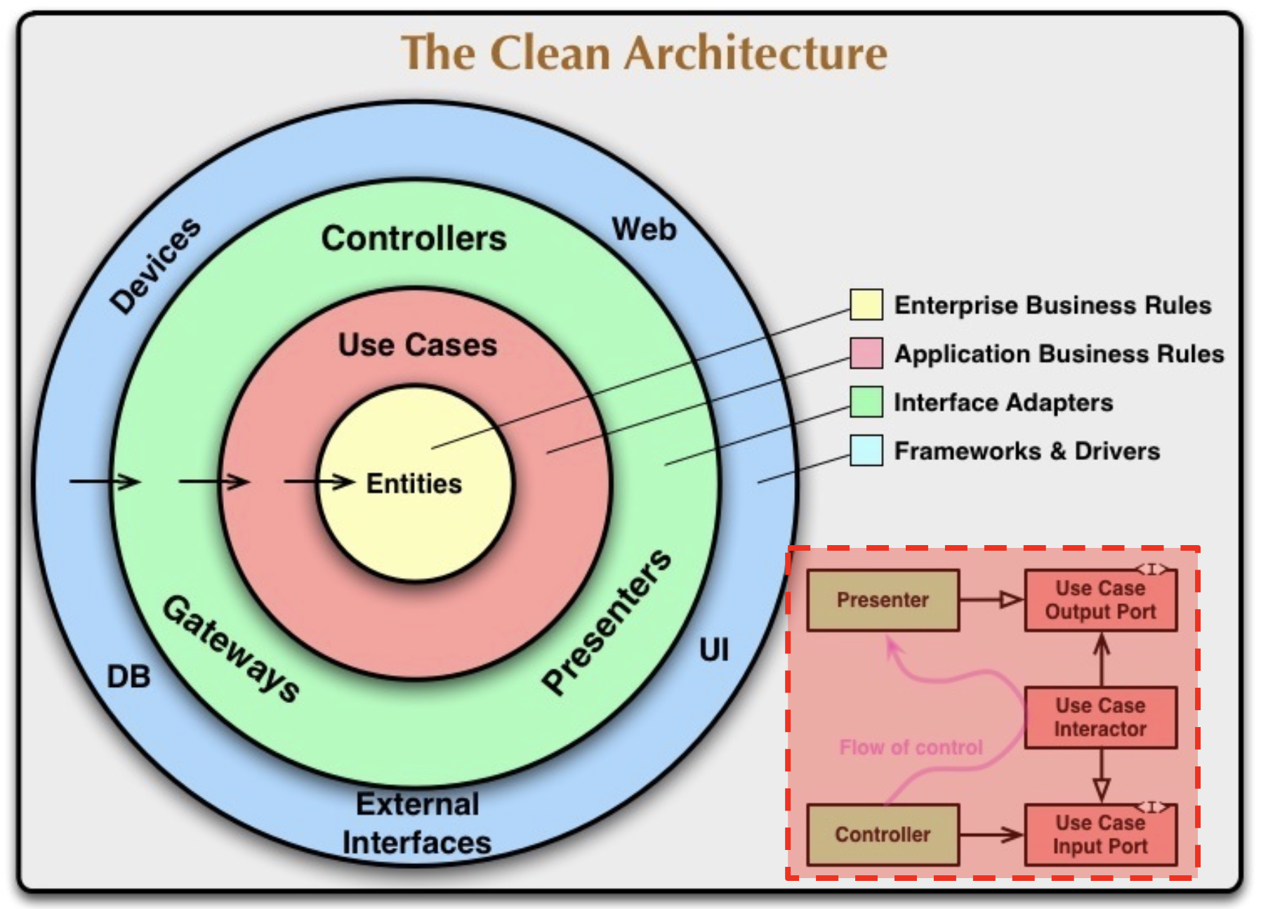 Image source: https://blog.cleancoder.com/uncle-bob/2012/08/13/the-clean-architecture.html However, a potential issue arises when considering use cases like booking an appointment. How can the use case access the database to save the appointment if it cannot directly interact with the adapter responsible for the database? This would seem to violate the flow of dependency.
To address this, the bottom-right sub-diagram provides a solution. We observe a controller and a presenter on the left-hand side, both serving as examples of adapters. On the right-hand side, the use case is divided into three components. At the center, we have the use case interactor, which contains the logic governing the use case. At the bottom, there is an input port, while at the top, there is an output port. The uppercase “I” in the corner signifies that these ports are interfaces. The use case input port is satisfied by the controller, while the use case output port is implemented or satisfied by the presenter.
In JavaScript, the notion of interfaces may not be familiar to those primarily accustomed to JavaScript programming. However, the concept can be achieved by practicing dependency injection rather than direct imports. Fortunately, injecting dependencies is relatively straightforward in JavaScript.
That’s all? - Nope!
The number of circles depicted in the diagram is not fixed. The circles are presented as a schematic representation, and in practice, we may require more than just four circles. The key principle, however, is that the Dependency Rule always applies. The dependencies in the source code always point inwards, regardless of the number of circles.
As we move towards the inner circles, the level of abstraction increases. The outermost circle represents low-level concrete details, while moving inwards encapsulates higher-level policies. The innermost circle represents the most general and abstract concepts. Therefore, the specific number of circles can vary, but the overall concept remains the same.
Conclusion
The diagram may appear confusing at this stage since we haven’t delved into the practical implementation details. In the upcoming blog, I will provide a comprehensive explanation of each layer along with code examples, which will help clarify how the architecture can be effectively implemented in actual code.